


What are Logic Gates?
Logic Gates form the basis of today’s digital infrastructure and are immensely important. They form a salient part of our digital world thus helping in making day-to-day tasks easier and less time-consuming. The term logic gates is made up of two words logic and gate, the former means operators who produce a result based on a logical equation whose answer is either yes or no, and the latter is used because these operators are usually used for gatekeeping in the electrical industries. Thus we can conclude that logic gates are operators like logical and gates.
They are mainly based on two binary digits, 1 and 0 which each represent ON and OFF functioning of the devices. Based on this binary system we have various different types of logic gates performing different calculations thus having various different applications. Some examples of logic gates are: NOT Gate which works as an inverter, OR gate, AND gate, NOR gate, NAND gate, XOR gate, etc.
Truth Table and Logic Gates
The Truth Table is the visual representation of all the combinations of inputs and the outputs thereof, stored in a tabular format. They uncomplicated working with the Logic Gates.
Tautology: When the output is true(1)
Fallacy: When the output is False(0)
Example of a Truth Table
Logical Operators
1. NOT or Negation:
It is the only operator which works with only one variable at a time thus is termed as an Unary Operator. Its most common symbol is ~. It returns 1 for 0 and 0 for 1, that is it negates.
The truth table for the operator is:
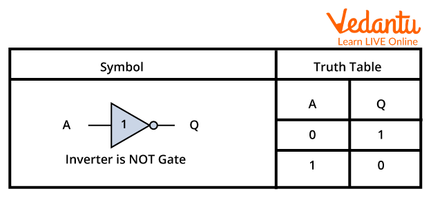
Symbol and Truth Table for NOT Operator
2. AND or Conjunction Operator:
It is a binary operator that is it works on two variables at a time, it may work with even more than two operands at a time. Its mathematical basis is A.B that is multiplication. It is represented by the symbol: “.”
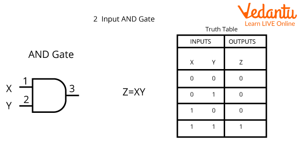
Symbol and Truth Table for AND Operator
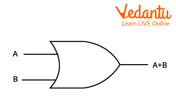
3. OR or Disjunction Operator:
It is another example of a binary operator but it can also work with more than two operands at a time. Its mathematical basis is addition of the two operands. Its symbol is +
The Truth Table is given as:
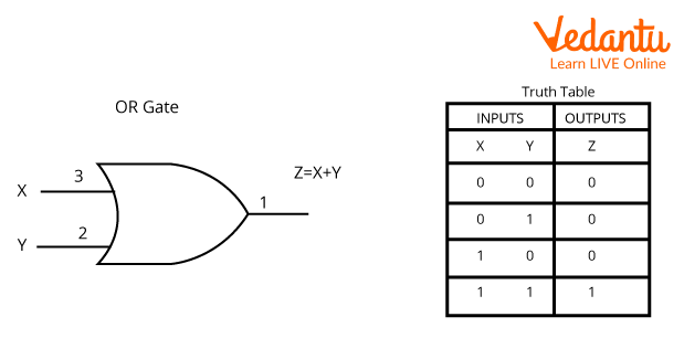
Symbol and Truth Table for OR Gate
Logical Expression for NAND Gate
The NAND Gate is the combination of AND and NOT gate. In this section we will talk about the logical expression for NAND gate.
Mathematically, it first multiplies the two operands and then inverts the answer, for example: if our two inputs are 1 and 1 then it will first perform 1x1=1 followed by inverting it to 0 thus our final result will be 0.
State the logical expression for nand gate:
The logical expression for nand gate is: \[]\bar{A.B}\
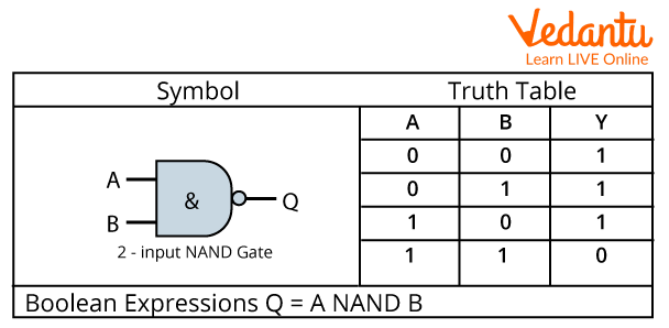
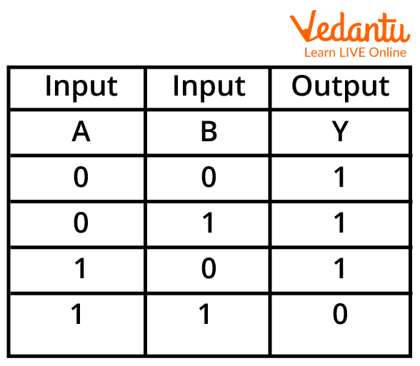
Symbol and Truth Table for NAND Gate
Summary
The logic gates form the fundamental part of digital devices and are responsible for performing the basic calculation behind the working of the devices. They follow the binary system of numbers which include 1 and 0 representing ON and OFF states of the devices, respectively. We have different types of logic gates like NOT, OR, AND, NAND, NOR, etc.
Sample Questions
1. Write the truth table for the following logical operators:
AND
NAND
Ans:
AND Gate:
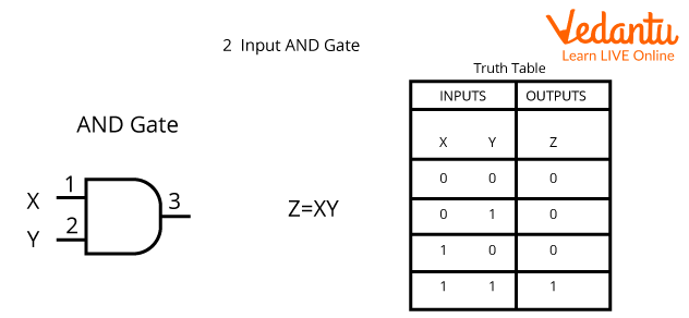
AND Gate
NAND Gate:
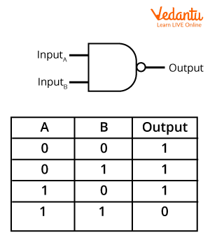
NAND Gate
2. Give the symbol representing the following logic operators:
NOT
OR
Ans:
NOT Gate:
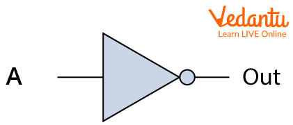
NOT Gate
OR Gate:
OR Gate
Practice Questions
Calculate the output for the inputs in the NAND Gate:
A=1; B=0
A=1; B=1
Answers:
1
0
State the type of gates based on the data given:
Input: A=1; B=0, Output: Y=0
Input: A=0; B=0, Output: Y=1
Answers:
NOR Gate
NAND Gate


FAQs on Logic Gates and Number System
1. What are the four main types of number systems used in Computer Science?
The four fundamental number systems specified in the CBSE syllabus are:
- Decimal (Base-10): The everyday number system we use, with digits 0 through 9.
- Binary (Base-2): The most fundamental system for computers, using only two digits: 0 and 1.
- Octal (Base-8): Uses digits 0 through 7 and is sometimes used as a more compact way to represent binary numbers.
- Hexadecimal (Base-16): Uses digits 0-9 and letters A-F. It is widely used in programming and memory addressing for its concise representation of binary data.
2. Why is the binary number system so important for modern digital computers?
The binary number system is fundamental to computers because all digital electronics operate on a two-state system. The internal circuits of a computer, like transistors, exist in one of two states: ON or OFF. These two states are perfectly represented by the binary digits (bits) 1 (ON) and 0 (OFF). This simplicity makes the design of logic circuits more reliable, efficient, and less prone to errors compared to systems with more voltage levels.
3. What are the seven basic types of logic gates?
The seven basic logic gates that are the building blocks of digital circuits are:
- AND Gate: Outputs 1 only if all inputs are 1.
- OR Gate: Outputs 1 if at least one input is 1.
- NOT Gate: An inverter that outputs the opposite of its single input.
- NAND Gate: Outputs the opposite of an AND gate.
- NOR Gate: Outputs the opposite of an OR gate.
- XOR Gate (Exclusive OR): Outputs 1 only if the inputs are different.
- XNOR Gate (Exclusive NOR): Outputs 1 only if the inputs are the same.
4. How are NAND and NOR gates considered 'universal gates'?
NAND and NOR gates are called universal gates because any other basic logic function (AND, OR, NOT) can be created by using only NAND gates or only NOR gates. For example, connecting both inputs of a NAND gate together makes it function as a NOT gate. This property is extremely valuable in integrated circuit (IC) design, as it allows complex circuits to be built using just one type of gate, simplifying the manufacturing process.
5. What is the primary function of a logic gate in a digital system?
The primary function of a logic gate is to act as a fundamental building block for digital circuits. It takes one or more binary inputs (0s and 1s) and performs a specific logical operation based on its design (e.g., AND, OR, NOT) to produce a single binary output. All complex operations performed by a computer, from simple arithmetic to complex processing, are ultimately broken down into a series of these simple logical operations performed by gates.
6. What is the key difference between an OR gate and an XOR gate?
The key difference lies in how they handle the case where both inputs are true (1). An OR gate follows an inclusive logic: it outputs 1 if one input OR the other input OR both are 1. In contrast, an XOR (Exclusive OR) gate follows an exclusive logic: it outputs 1 only if one input OR the other is 1, but not both. If both inputs are the same (both 0 or both 1), the XOR gate outputs a 0.
7. How do you convert a decimal number to its binary equivalent? Explain with an example.
To convert a decimal number to binary, you use the repeated division-by-2 method. You continuously divide the decimal number by 2 and record the remainder after each division. You continue this process until the quotient becomes 0. The binary equivalent is the sequence of remainders read from the bottom up.
Example: Convert decimal 21 to binary.
- 21 ÷ 2 = 10 Remainder 1
- 10 ÷ 2 = 5 Remainder 0
- 5 ÷ 2 = 2 Remainder 1
- 2 ÷ 2 = 1 Remainder 0
- 1 ÷ 2 = 0 Remainder 1
Reading the remainders from bottom to top, the binary equivalent of decimal 21 is 10101.
8. Can you give some real-world examples of logic gates in action?
Yes, logic gates are used in many everyday devices:
- AND Gate: A safety feature in a microwave oven that requires the door to be shut (Input 1 is HIGH) AND the start button to be pressed (Input 2 is HIGH) for it to operate.
- OR Gate: A home's doorbell system might have a front doorbell button and a back doorbell button. Pressing either button (or both) will make the chime ring.
- NOT Gate: The light inside a refrigerator. When the door is closed (input is 1), the light is off (output is 0). When the door is open (input is 0), the light turns on (output is 1).
- NAND Gate: A simple burglar alarm. The alarm (output) is OFF (0) only when the system is armed (Input 1 is ON) AND the window sensor is closed (Input 2 is ON). If either is OFF, the alarm sounds.
9. What are Boolean Laws and why are they important for simplifying logic circuits?
Boolean Laws, or the laws of Boolean Algebra, are a set of rules (such as Commutative, Associative, Distributive, and De Morgan's laws) used to analyse and manipulate logical expressions. They are extremely important because they allow digital circuit designers to simplify complex logical expressions. By simplifying an expression, you can reduce the number of logic gates required to build the circuit. This makes the final circuit cheaper to produce, faster in operation, and more energy-efficient.